高度なレッドストーン回路(英:Advanced Redstone Circuits)には、複雑なレッドストーン回路を必要とするメカニズムが存在します。これらは通常、論理ゲートなどの多くの単純な装置で構成されています。より単純なメカニズムについては、電子メカニズム、レッドストーン、ワイヤー式トラップを参照してください。
コンピュータ
Minecraftでは、いくつかのゲーム内システムで効率的に情報を処理することができます。そのシステムは水、砂、トロッコ、ピストン、レッドストーンなどです。これらすべてのシステムのうち、レッドストーンのみが特別にレッドストーン信号という形式を使い、情報を処理するために追加されました。
レッドストーンは電気と同様に信頼性が高く、切り替えスピードが速いため、電気が空気圧などの様々な機会を追い越して我々の世界の先端技術になったように、Minecraftの先端技術として他の機械システムを追い越してきました。
現代のデジタル回路でもレッドストーン工学でも、複雑な情報処理系の要素の構築は複数の抽象化された層を用いて簡略化されています。
第1層は原子部品の層で、レッドストーン、レッドストーントーチ、レッドストーンブロック、レッドストーンリピーター、感圧板、ピストン、ボタン、レバーの全てがレッドストーン信号に影響を与えることができます。
第2層は2進論理ゲートです。これは複合デバイスで、非常に限定された内部状態を有し、通常は1〜3ビットで動作します。
第3層は論理ゲートを組み合わせて作られたハイレベルな構成要素です。これらの装置はビットのパターンで動作し、頻繁に自然数など人間にとってよりわかりやすい形に翻訳し、抽象化します。このような装置には数学的加算器、組み合わせ錠、記憶レジスタなどがあります。
第4層および最終層では、主要な構成要素の組が組み合わされて、しばしばユーザーの監督なしで任意のデータを処理できる機能的なコンピュータシステムを作成します。
.png)
8ビットレジスタページは抽象化部品の第3層にあります。
変換器
これらの回路は、与えられた形式の入力を別の形式に変換するのみです。変換器には、2進→BCD、2進→10進、2進→16進、BCD→7セグメントなどがあります。
ピストンマスク分波器
この設計は、ANDゲートを組み合わせたものと理解してよいでしょう。
分波器は、次のような論理を使った回路です。
出力0 = (~bit2) & (~bit1) & (~bit0)
出力1 = (~bit2) & (~bit1) & (bit0)
といった具合です。
分波器を実装する一番わかりやすい方法は、論理ゲートを何個も並べて接続することですが、3桁や4桁でもめちゃくちゃになってしまいます。
2進数の表を見てみると、あるパターンがある事に気づくでしょう。
| N | Bit2 | Bit1 | Bit0 |
|---|---|---|---|
| 0 | 0 | 0 | 0 |
| 1 | 0 | 0 | 1 |
| 2 | 0 | 1 | 0 |
| 3 | 0 | 1 | 1 |
| 4 | 1 | 0 | 0 |
| 5 | 1 | 0 | 1 |
| 6 | 1 | 1 | 0 |
| 7 | 1 | 1 | 1 |
桁数をQとすると、最上桁はQ/2の数値を反転させ、次の桁はQ/4の数値を反転させ、Q番目の桁に到達するまで繰り返します。
したがって、このような回路を作る必要があります:

ここで、緑の三角形は非反転、赤の三角形は反転します。黒い線は想像上のANDゲートです。また、上は最下桁、下は最上桁を表します。
これを簡単に実現するには、ブロックと空気で構成された3枚の「パンチカード」を使います。「パンチカード」やマスクは、スライムブロックを使ってピストンで動かしています。
つまり、3層のマスクのすべてが特定の方法で整列している場合にのみ、信号が伝播していることになります。
ファイル:Bits demux38.png写真を開くと層を見られます。
ご覧のように、この仕組みは非常に小型で分かりやすいです。
これを逆にして使うこともできます(多重化器としてではありませんが、リピーターを逆にすると、全ての過出力(0~7)からの信号は、分波器の現在の状態と一致する場合にのみ伝搬するので、「出力3 = (入力3) AND (Demux=011)」のように動作します)。
2進数→8進数

3桁二進数→8進数のゲート。
3桁の二進数入力を多数のうち1つの起動線に変換する一連のゲートです。大きくても5×5×3と小型なので、色々な意味で便利です。
暗黙的論理和を使用して結合された線が多数あるため、信号が他の入力に負帰還されないように、各入力の前に一方通行装置を配置して回路を構成する必要があります。
各出力線の要件(分離一方通行装置を除く):
| 数 | 0 | 1 | 2 | 3 | 4 | 5 | 6 | 7 |
|---|---|---|---|---|---|---|---|---|
| 大きさ | 5×3×2 | 5×3×3 | 5×5×3 | 5×5×3 | 5×3×3 | 5×4×3 | 5×5×3 | 5×5×3 |
| トーチ | 1 | 2 | 2 | 3 | 2 | 3 | 3 | 4 |
| レッドストーン | 7 | 7 | 12 | 10 | 7 | 7 | 10 | 10 |
2進数→16進数または10進数
4ケタの二進数入力を、多数の内の1つの起動線に変換する一連のゲートです(例えば、入力が10進数の場合は0~9、16進数の場合は0~F)。これらは最大でも3×5×2と小型なので、様々な意味で便利です。
暗黙的論理和を使用して結合された線が多数あるため、信号が他の入力に負帰還されないように、各入力の前に一方通行装置を配置して回路を構成する必要があります。

4桁二進数→16進数のゲート
各出力線の要件(分離一方通行装置を除く):
| 数 | 0 | 1 | 2 | 3 | 4 | 5 | 6 | 7 | 8 | 9 | A | B | C | D | E | F |
|---|---|---|---|---|---|---|---|---|---|---|---|---|---|---|---|---|
| 大きさ | 3×3×2 | 3×4×2 | 3×4×2 | 3×4×2 | 3×4×2 | 3×5×2 | 3×5×2 | 3×5×2 | 3×4×2 | 3×5×2 | 3×5×2 | 3×5×2 | 3×5×2 | 3×5×2 | 3×5×2 | 3×5×2 |
| トーチ | 1 | 2 | 2 | 3 | 2 | 3 | 3 | 4 | 2 | 3 | 3 | 4 | 3 | 4 | 4 | 5 |
| レッドストーン | 2 | 2 | 2 | 2 | 2 | 2 | 2 | 2 | 2 | 2 | 2 | 2 | 2 | 2 | 2 | 2 |
16進数→2進数
また、16進数の信号を4桁の2進数に変換することもできます。必要なのはORゲート4つのみで、それぞれ8つの入力があります。これらは、信号が他の入力に負帰還されるのを防ぐために、ORを分離する必要があります。
For every output line, make an OR gate with the inputs wired to the input lines where there is a '1' in the table below.
| Number | 0 | 1 | 2 | 3 | 4 | 5 | 6 | 7 | 8 | 9 | A | B | C | D | E | F |
|---|---|---|---|---|---|---|---|---|---|---|---|---|---|---|---|---|
| 4-bit | 0 | 0 | 0 | 0 | 0 | 0 | 0 | 0 | 1 | 1 | 1 | 1 | 1 | 1 | 1 | 1 |
| 3-bit | 0 | 0 | 0 | 0 | 1 | 1 | 1 | 1 | 0 | 0 | 0 | 0 | 1 | 1 | 1 | 1 |
| 2-bit | 0 | 0 | 1 | 1 | 0 | 0 | 1 | 1 | 0 | 0 | 1 | 1 | 0 | 0 | 1 | 1 |
| 1-bit | 0 | 1 | 0 | 1 | 0 | 1 | 0 | 1 | 0 | 1 | 0 | 1 | 0 | 1 | 0 | 1 |
Example

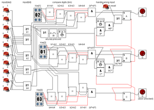
Logic for a 3-digit key log, with digits 0-9. It's order-sensitive
The example on the right uses ORs (>=1), [./https://minecraft.gamepedia.com/Logic_circuit#XNOR_Gate XNORs] (=), [./https://minecraft.gamepedia.com/Memory_circuit#RS_NOR_Latches RS NOR latches] (SR) and some [./https://minecraft.gamepedia.com/Redstone_Repeater delays] (dt*). For the XNORs I would prefer the C-design.
The example on the right uses a 4-bit design, so you can handle a hexadecimal key. So you can use 15 various digits, [1,F] or [0,E]. You only can use 15, because the state (0)16 = (0000)2 won't activate the system. If you want to handle 16 states, you edit the logic, to interact for a 5-bit input, where the 5th bit represents the (0)16 state.
In the following we'll use (0)16 = (1111)2. And for [1,9] the MUX-table upon. So the key uses decimal digits. Therefore, we have to mux the used buttons to binary data. Here look through the first two columns. The first represents the input-digit in (hexa)decimal, the second represents the input-digit in binary code. Here you can add also buttons for [A,E], but I disclaimed them preferring a better arranging. The /b1\-box outputs the first bit, the /b2\-box the second, and so on.
Now you see Key[i] with i=1..3, here you set the key you want to use. The first output of them is the 1-bit, the second the 2-bit and so on. You can set your key here with levers in binary-encryption. Use here the MUX-table upon, and for (0)h := (1111)2. If we enter the first digit, we have to compare the bits by pairs (b1=b1, b2=b2, b3=b3, b4=b4). If every comparison is correct, we set the state, that the first digit is correct.
Therefore, we combine (((b1=b1 & b2=b2) & b3=b3) & b4=b4) =: (b*=b*). In minecraft we have to use four ANDs like the left handside. Now we save the status to the RS-latch /A\. The comparison works the same way for Key[2], and Key[3].
Now we have to make sure, that the state will be erased, if the following digit is wrong. Therefore, we handle a key-press-event (--/b1 OR b2 OR b3 OR b4\--/dt-\--/dt-\--). Search the diagram for the three blocks near "dt-". Here we look, if any key is pressed, and we forward the event with a minor delay. For resetting /A\, if the second digit is wrong, we combine (key pressed) & (not B). It means: any key is pressed and the second digit of the key is entered false. Therewith /A\ will be not reset, if we enter the first digit, /A\ only should be reset, if /A\ is already active. So we combine (B* & A) =: (AB*). /AB*\ now resets the memory-cell /A\, if the second digit is entered false and the first key has been already entered. The major delay /dt+\ must be used, because /A\ resets itself, if we press the digit-button too long. To prevent this failure for a little bit, we use the delay /dt+\. The OR after /AB*\ is used, for manually resetting, i.e. by a pressure plate.
Now we copy the whole reset-circuit for Key[2]. The only changes are, that the manually reset comes from (not A) and the auto-reset (wrong digit after), comes from (C). The manual reset from A prevents B to be activated, if the first digit is not entered. So this line makes sure, that our key is order-sensitive.
The question is, why we use the minor-delay-blocks /dt-\. Visualize /A\ is on. Now we enter a correct second digit. So B will be on, and (not B) is off. But while (not B) is still on, the key-pressed-event is working yet, so A will be reset, but it shouldn't. With the /dt-\-blocks, we give /B\ the chance to act, before key-pressed-event is activated.
For /C\ the reset-event is only the manual-reset-line, from B. So it is prevented to be activated, before /B\ is true. And it will be deactivated, when a pressure-plate resets /A\ and /B\.
- Pros
- You can change the key in every digit, without changing the circuit itself.
- You can extend the key by any amount of digits, by copying the comparison-circuit. Dependencies from previous output only.
- You can decrease the amount of digits by one by setting any digit (except the last) to (0000)2.
- You can open the door permanently by setting the last digit to (0000)2
- Cons
- The bar to set the key will be get the bigger, the longer the key you want to be. The hard-coded key-setting is a compromise for a pretty smaller circuit, when using not too long keys. If you want to use very long keys, you also should softcode the key-setting. But mention, in fact the key-setting-input will be very small, but the circuit will be much more bigger, than using hard-coded key-setting.
Not really a con: in this circuit the following happens with maybe the code 311: 3 pressed, A activated; 1 pressed, B activated, C activated. To prevent this, only set a delay with a repeater between (not A) and (reset B). So the following won't be activated with the actual digit.
If you fix this, the circuit will have the following skill, depending on key-length. ( digit = 2n-1, possibilities: digitLength )
| Length | 1 | 2 | 3 | 4 | 5 |
|---|---|---|---|---|---|
| 2 bit | 3 | 9 | 27 | 81 | 243 |
| 3 bit | 7 | 49 | 343 | 2.401 | 16.807 |
| 4 bit | 15 | 225 | 3.375 | 50.625 | 759.375 |
| 5 bit | 31 | 961 | 29.791 | 923.521 | 28.629.151 |
Miscellaneous
Combination Locks
Tutorials/Combination locks
Sorting Device
This is a device which sorts the inputs, putting 1s at the bottom and 0s at the top, in effect counting how many 1s and how many 0s there are. It is designed so that it is easily expandable, as shown in the diagram. The 5×5 center square is tileable. The inputs are at the bottom and right and the outputs are at the top and left
Truth table for a three-bit sorting device:
| A | B | C | 1 | 2 | 3 |
|---|---|---|---|---|---|
| 0 | 0 | 0 | 0 | 0 | 0 |
| 1 | 0 | 0 | 1 | 0 | 0 |
| 0 | 1 | 0 | 1 | 0 | 0 |
| 0 | 0 | 1 | 1 | 0 | 0 |
| 1 | 1 | 0 | 1 | 1 | 0 |
| 0 | 1 | 1 | 1 | 1 | 0 |
| 1 | 0 | 1 | 1 | 1 | 0 |
| 1 | 1 | 1 | 1 | 1 | 1 |
Timer
Timers can detect the time difference between the first input and the second.
2
|
||||
1
|
The amount of time can be determined by how far the signal travels. For example, if 5 of the locked repeaters are powered, it means the time difference was 0.4-0.5 seconds, ignoring lag. If the time difference is exactly 0.4 seconds, 4 repeaters will be powered.
The repeaters that will lock can be set to different delays. For example, if they are set to 4 ticks and the first 3 are active, it means the time difference was 0.8-1.2 seconds. You can even have a mix, which can be handy if you know what the range is likely to be. However, you will need to be careful when reading these timers.
If you are measuring higher scales, the second signal might not reach all of the repeaters. You will need repeaters to replenish the signal.
If the signals are short times (like if you are using [./https://minecraft.gamepedia.com/Observer observers]), you may not have time to read the data.
2
|
1
| |
You can also measure how long a signal lasts.
Please note the following when making a duration timer:
- Because of the delay that the redstone torch adds, the delay of the initial repeater, the one that stays unlocked, must be increased to 2 ticks.
- The data from the timer will be preserved.
- Because the repeaters will still be powered when the timer is used again, the circuit must be obstructed between uses in order to unlock the repeaters. To do this mine the [./https://minecraft.gamepedia.com/Redstone_torch redstone torch], wait for all of the repeaters to deactivate, and put the redstone torch back.
Serial interface lock with D flip-flops
ファイル:Serial lock LogicCircuit.png
D flip-flop is an electronic component that allows you to change its output according to the clock. It's and RS NOR latch that sets its value to the D input when the ">" (clock) input is changing its state from low to high (in some cases from high to low).
Basically, it's equivalent to the expression: "Set the output Q to the input D when the input C goes from 0 to 1".
For example, you can use D flip-flops to shift the value from left to right.
In this lock, the > signal propagates from the rightmost flip-flop to the leftmost, so the signal shifts to the right. This circuit allows you to input a 4-bit number with two levers. You can use any number of bits, but this configuration is already pretty secure even if someone figures out what a lock it is.
So, if you want to input the combination 1-0-1-0, follow these steps:
- D = 1
- > = 1
- > = 0
- D = 0
- > = 1
- > = 0
- D = 1
- > = 1
- > = 0
- D = 0
- > = 1
- > = 0
In theory, you can program the lock from this serial interface as well. Just attach 4 RS NOR latches and a hidden place for the programming levers.
This design is not very practical as a lock, but might be a nice feature on something like a puzzle challenge map.
See also
- [./https://minecraft.gamepedia.com/Redstone_circuit Redstone circuits]
- [./https://minecraft.gamepedia.com/Tutorials/Mechanisms Mechanisms]
- [./https://minecraft.gamepedia.com/Tutorials/Traps Traps]
| 新人向け |
| ||||||||||||
|---|---|---|---|---|---|---|---|---|---|---|---|---|---|
| 全般 | |||||||||||||
| チャレンジ |
| ||||||||||||
| 建築 | |||||||||||||
| 生産 |
| ||||||||||||
| エンチャントと製錬 | |||||||||||||
| ブロック破壊 |
| ||||||||||||
| メカニズム |
| ||||||||||||
| サーバー |
| ||||||||||||
| 技術的なチュートリアル |
| ||||||||||||
| 古いチュートリアル |
| ||||||||||||